eDocs Home > BEA AquaLogic Data Services Platform Documentation > Data Services Developer's Guide > Contents
Modeling Data Services
This section provides a basic overview of modeling in ALDSP and a tutorial.
Topics
Introduction
Using ALDSP, you can create and maintain models of your enterprise data services. A model diagram is a graphical representation of a data model supported by ALDSP.
Through data models you can:
- Model a high-level, visual view of data resources.
- View and extend relationships between data services.
- Access and create a data service.
- Add operations to a data service.
- Change the XML type (schema) associated with a data service.
In model diagrams, a relationship can be created by the gesture of drawing a line from one data service to another. In some cases (such as relational data services) relationships and the lines representing the relationship can be automatically inferred. In other cases, you need to create the relationship.
A visual representation of a relationship between two data services conveys a considerable amount of information:
- Cardinality. Is the relationship one-to-zero (customers and promotional offers), one-to-one (customer and primary email), one-to-many (customers and orders), or many-to-many (customer orders and ordered items)?
- Direction. Arrows indicate possible navigation paths. Is there an originating entity associated with a subordinate entity (such as orders and order items) or is the relationship bidirectional (such as customers and orders)?
- Roles. A name matching the name of the adjacent data services navigation function (see below). Does the assigned relationship name capture the purpose of the navigation function it represents?
Navigation functions are visible as properties of each data service in a binary relationship. Navigation functions also appear as mouse-over text over each endpoint of the relationship line.
Types shown in model diagrams are XML schema types.
| For more information on data service modeling concepts see Modeling and a Service-Oriented Architecture in the ALDSP 2.5 Concepts Guide. |
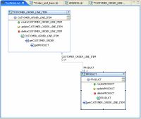
Model Diagram of Physical Data Services
Building a Simple Data Service Relationship Model
You can create a sample data service relationship model by selecting a dataspace project and choosing:
File > New > Relationship Modeler
You can locate your model diagram anywhere in your project. Any legal filename can be used.
About the Data Services
This example assumes that you are using the ALDSP RTLApp as a data source.
The physical data services used in this sample are:
- CUSTOMER
- CUSTOMER_ORDER
- CUSTOMER_ORDER_LINE_ITEM

Creating and Updating Physical Data Services
Adding Data Services to the Modeler
You can add data services to your model using simple drag-and-drop from the Project Explorer. In the Project Explorer you can multi-select data services using either:
- Shift-click (contiguous services) or
- Control-click (individual services)
If you drag a set of data services into a model diagram, existing relationships to other data services in the model will be shown.
Populating the Relationship Modeler
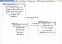
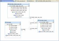
Since the data services in this example are representations of relational sources, a several bidirectional relationships between CUSTOMER_ORDER and CUSTOMER_ORDER_LINE_ITEMS were inferred:
- The role named CUSTOMER_ORDER has a 1-to-1 relationship with CUSTOMER_ORDER_LINE_ITEM, meaning that a line item can only belong to one order.
- The role named CUSTOMER_ORDER_LINE_ITEM has a 0-to-n relationship with CUSTOMER_ORDER, meaning meaning that there can be many line items associated with an order.
Creating an Additional Relationship
A next step could be to create a relationship between CUSTOMER and CUSTOMER_ORDER.
- Right-click on CUSTOMER_ORDER node.
- Select Create Relationship to another data service.
- Select CUSTOMER as the target data service.
- Click OK.
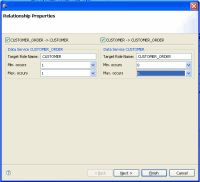
The Relationship Properties wizard appears.
Setting Relationship Properties
Relationship properties can be uni- or bi-directional.
Setting Relationship Options
Relationship Properties Dialog Options
| Option | Action |
Comment/Reference |
|---|---|---|
| Set directionality |
Select the directions to be supported in the relationship. The example is bidirectional so the default checked condition for the following relationships need not be changed:
|
Creating relationships in a model automatically creates relationship functions between data services. Bi-directional settings mean that "get" functions for the related data service will be created on both sides of the relationship. By default, relationships are bidirectional. |
| Target Role Name |
Enter the name of the role function. In the example, default names can be used:
|
By default the name will be based on the name of the related data service. It can be changed to any unique and legal name in your dataspace project. |
| Set maximum and minimum occurances | Enter cardinality settings for the respective function. For the example the following settings are used:
|
The minimum and maximum occurrence settings definite the nature of the relationship between the two services. |
Click Next.
Configuring Navigation Functions
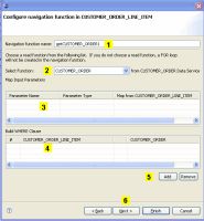
Each navigation function (one or two) being created also needs to be configured. Configuration includes:
- Setting a name for the navigation function
- Selecting a function from the newly related data service.
- Mapping input parameters
- Building a WHERE clause
Configuring a Navigation Function
Specifying Relationship Wizard Function Name, Parameters, and Where Clauses
| Element | Purpose | ||
|---|---|---|---|
| Navigation function name | By default, the navigation function name is the name of the target data service with "get" prepended, as in "getCustomer". If a function of that name exists, numbers will be appended to the function name as in getCustomer1.
|
||
| Related data service function | By default, the root function in the target data service is selected. However, you can select any available read function in the target data service. | ||
| Map input parameters | If the related function has input parameters, the name and type of the available parameters appear. You can then use a pulldown menu to select an element from the target data service to map as the input parameter. | ||
| Build WHERE clause | Where clauses can be added to the function using pulldown menus that allow you to select join elements from each side of the relationship. | ||
| Add or Remove | Allows you to add additional where clauses or delete an identified where clause. | ||
| Next | When the relationship between data services is bidirectional clicking Next changes the focus to the second data service, where you can identify a navigation function name, parameters, and add where clauses for the second side of the relationship. |
